This material is availablle in very many different colors, but as we know the main advantage of it is that later whole product looks like it is made out of one piece instead of parts. This is the reason why this material is very commonly used to make shaped counters and public space products. Very common mistake is that engineers also draw them like this or just put milter joints everywhere.
But then how to make 3D model so that those parts can be cut ASAP without redrawing or even not using any drawings at all?
Corian parts can
be divided generally into horizontal parts (worktops and other main surfaces)
and vertical/side parts. The strongest and best way is to glue them to each other
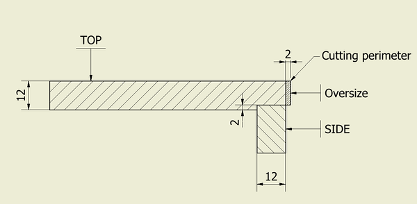
is shown here:
In order to get the perfect match between 2 surfaces they are machined and then polished. That is the reason why horizontal part needs to be drawn 2 mm oversize. As it changes product size on drawings I add this 2 mm after confirmation from architect. Sometimes it is even needed to delete connection lines on the 3D view to give them 1 piece look. That all pays off because after adding the oversize You can generate 2D DWG-s of all parts and straight import them into Your CNC programming software without using any drawings and start cutting right away!
But what will happen to shaped vertical parts ?
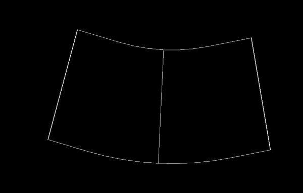
Those are smart to convert into sheet metal in Your CAD software, because then can make automatic flat patterns and those can be converted into DWG that can be straight imported into CNC programming software. I personally use drawing generator that does all this process automatic. When extra oversize needed that can be added in Flat pattern environment that does not affect 3D model and general drawings. A flat pattern DWG of shaped part is shown here:
Next up is stuff that is also sometimes used in those counters - frameworks and metal tubes


72 replies